
LOW COST OPTICAL DIGITISING
| MENU | |
| Home | |
| Features | |
| Downloads | |
| About Rigs | |
| Purchasing | |
| How It Works | |
| Screen Shots | |
| Contact Us | |
| TUTORIALS | |
| Tutorial 1 | |
| Tutorial 2 | |
| Tutorial 3 | |
| Tutorial 4 | |
| Tutorial 5 | |
| Tutorial 6 | |
| Tutorial 7 |
Tutorial 1
Creating Points & Faces. Exporting.
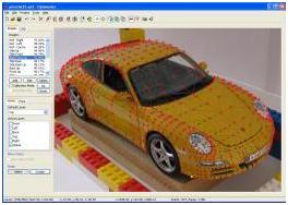
Open up the Tutorial1.op2 project file. This project is available on the downloads page.
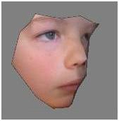
This project has four images, one material and one layer. All of the images have already been calibrated. The dots on the model are from a whiteboard marker, and wipe off once the images have been taken.
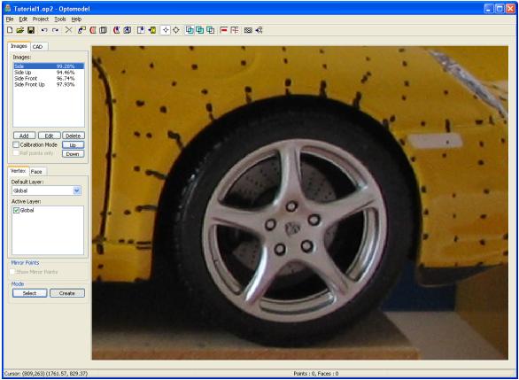
The Side image should be showing in the work area. If not, click on Side in the Images Tab.
The screen should look like this :
Navigating
Hold the CTRL key down while moving the mouse in the work area to get a feel for scrolling.
Point the mouse wheel at one point on the image and use the mouse wheel to zoom in and out. The image should zoom in and out while maintaining the mouse pointer over the same part of the image.
Return the image to how it looks above and press the shift key. The linked image should appear which is the image Side Up. If not, click on Side Up while holding the shift key to create the link. Press the shift key a few times to check the link has been established.
Scrolling and zooming also works on the linked image. For example, while holding down the shift key (to show the link image), hold the CTRL key and move the mouse.
Creating a point
To create a point, check that the Vertex tab is selected. This puts the system into point mode (face made will be used later). Also check that the Create button at the bottom of the tool pane has been selected. This puts the system into Create mode (rather than Select mode).
The cursor should be a cross. If its a circle, you are in select mode.
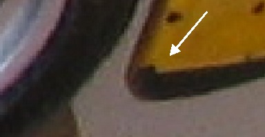
Ok, using the left mouse button, click on the centre of the black point shown below.
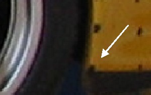
While holding down the Shift key, click on the centre of the black point shown below
A 3D point will be created and a red cross will appear over this point in the image. The screen should look something like this :
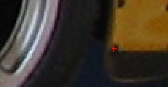
Click on some of the other images such as Side Front and Side Front Up to see how this point looks from the other available angles. It should be drawn on the same 3D of the model from all angles.
Saving the project
Having created a masterpiece of one point, lets save the project. On the File menu, choose Save As and save the project as Tutorial1A. This way, the original tutorial is not overwritten. From now on, just press the Save button on the toolbar.
Creating lots of points
Using the point creation method described above, create lots of points as shown below. If you make a mistake, use the Undo button on the toolbar.
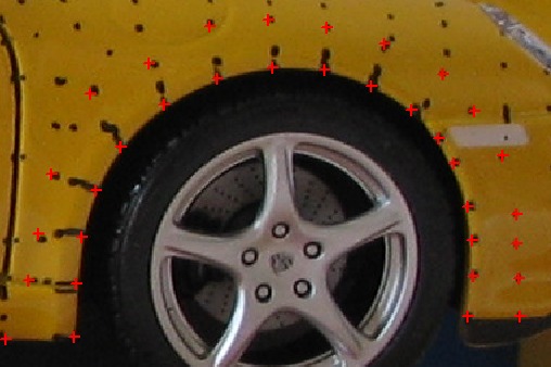
You dont have to click in the centre of these points. The objective is to choose a point that can be recognised in the linked image, so choose the edge of a point or the half way mark between points etc to get the 3D point exactly where you want it.
Creating a face
We have all these points, so lets create the polygons that join them up to form the mesh.
Click on the Face tab in the tools pane. This puts the system into face mode. The Create button should still be active, so we should still be in create mode. The cursor should now be a triangle.
We will start with the lower front part of the wheel arch as shown below. Click on the 3 points shown in order. Clockwise means the polygon will face towards us.
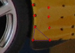
A black square will show over the first 2 selected points. When the third one is selected, the triangle will be created and the squares will clear. If you select the wrong points then press the ESC key to abort creating this face.
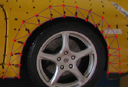
Creating lots of faces
Using the method described above, create a whole lot of faces as shown below. Dont forget, if you make a mistake, the undo button is available. Dont forget to save the project every now and then.
Exporting
We now have a mesh and want to see how it looks in 3D. From the Tools menu, choose Export. This is also available on the toolbar and is the last icon on the right.
You can choose OBJ or Direct-X. If the screen does not have the following settings, then change it to be the same and press OK.
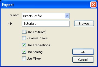
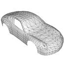
This creates an export file. Tutorial1.x in this case.
Here is the output as shown in Mview.exe.
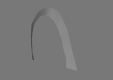
You could save the current project as Tutorial1B.op2 and try extending your mesh