
LOW COST OPTICAL DIGITISING
| MENU | |
| Home | |
| Features | |
| Downloads | |
| About Rigs | |
| Purchasing | |
| How It Works | |
| Screen Shots | |
| Contact Us | |
| TUTORIALS | |
| Tutorial 1 | |
| Tutorial 2 | |
| Tutorial 3 | |
| Tutorial 4 | |
| Tutorial 5 | |
| Tutorial 6 | |
| Tutorial 7 |
Tutorial 2
This tutorial is an extension to tutorial 1 and assumes that the user has already done tutorial1. The objective of this tutorial is to add images and calibrate them, ready for more point and face creation. This project is available on the downloads page.
Adding Images. Calibrating
Open up the Tutorial2.op2 project file.
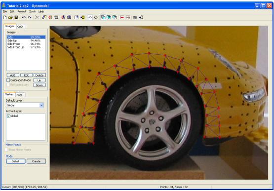
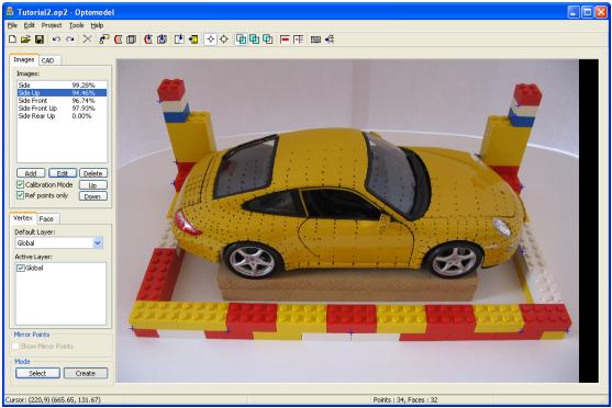
The screen should look like this :
Adding an Image
On the Images tab in the tool pane, click on the Add button. This will open the image properties form as shown below at the top left.
Click on the Browse button. The file dialog will open as shown below. If possible, click on the rightmost icon in this dialog and choose to view thumbnails to show a preview of all possible images.
Select IMG_2793.bmp.
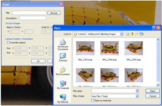
The file dialog will close. In the Description field of the image properties screen, type in Side Rear Up.
The properties form should look something like this :
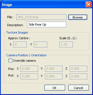
Press the OK button to close this form.
We now have a new image in the Images Tab, but it will need calibrating.
Calibrating
Click on the image Side Up.
Enter Calibration mode by checking the Calibration Mode check box.
The Ref Points only checkbox should be enabled. Check this too.
Zoom and scroll this image until the screen looks something like this :
While holding down the Shift Key, click on the Side Rear Up image.
Release the Shift key. Press the Shift key a few times to check that the images have been linked.
Click on this point in the image with the left mouse key. It should be selected as shown below:
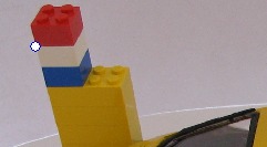
Hold down the Shift key and click on the same point of the model in the linked image. Use zooming and scrolling in the linked image to get lots of accuracy as shown below. This screen shot shows the point after it has been created.

Now release the Shift key.
This is how a known reference point can be reused without having to know the exact 3D coordinates.
Repeat this exercise on as many reference points from Side Up as are visible in Side Rear Up.
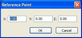
If you happen to get this form appear, then you have clicked too far from an existing reference point. This form is used for entering 3D points direct, when an existing point cannot be reused.
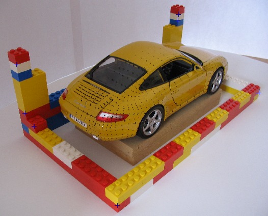
The image Side Rear Up should look something like this. Its hard to see, but there are blue crosses at the reference points.
When you uncheck the Calibration Mode checkbox, the following progress form will appear. The OK button will become enabled once processing has finished.
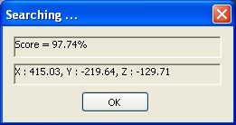
The existing points will map to the new image as red crosses.
To set a linked image for this new image, press the Shift key and click on the Side image. Toggle the shift key a few times to check that the link is ok.
Use zooming and scrolling of both images to find a point near the rear taillight, and create a point as described in tutorial 1.
The following images are of a point created with Side and Rear Side Up.
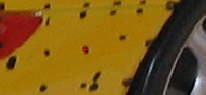
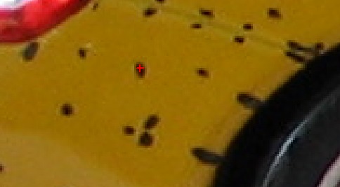
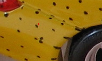
As a final note, be carefull of mixing point in the one area, from a lot of different image pairs. The following screen shot shows how the point above is mapped to the Side Up image. Note how it strays by a few pixels. This is quite normal.
In general do a large part of the model with one image pair, and other parts with their own image pairs. Keep a reasonable distance between sections of the model that have been created from different image pairs to avoid a noticeable seam.
Dont forget to save this project as something like Tutorial2a.op2 to keep the original tutorial project intact.