
LOW COST OPTICAL DIGITISING
| MENU | |
| Home | |
| Features | |
| Downloads | |
| About Rigs | |
| Purchasing | |
| How It Works | |
| Screen Shots | |
| Contact Us | |
| TUTORIALS | |
| Tutorial 1 | |
| Tutorial 2 | |
| Tutorial 3 | |
| Tutorial 4 | |
| Tutorial 5 | |
| Tutorial 6 | |
| Tutorial 7 |
Tutorial 6
This tutorial assumes that the user has already done tutorial1 and is familiar with the concepts in tutorial 4. This project is available on the downloads page.
The objective of this tutorial is to show how textures can be assigned to the model.
Texture Mapping
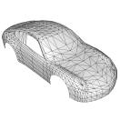
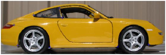
Open up the tutorial6.op2 project file. The project contains all of the images, points and faces of a model porsche.
This project has a material created for the right side of the model, but needs a texture for this side.
Adding the texture image
The first thing well do is add the texture view for the right hand side. To do this, click on the Add button in the Image tab.
Use the Browse button to select the file PorscheSkin.bmp.
Set the Description to Tex Right. It can be handy to use a naming convention to separate texture images from other measurement images.
screen should look something like this :
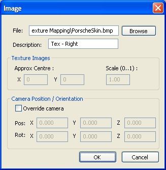
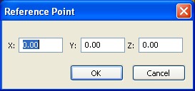
Press the OK button. The system will detect that the image supplied is not of the same width and height as the images that are native to the camera (Canon 4 MegaPixel in this case), so the following dialog box appears :
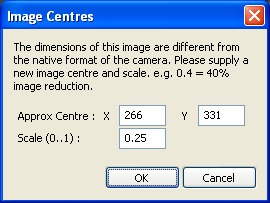
Enter the numbers are shown above. This bitmap contains many sides, but we are only interested in the right hand side. We set the coordinates where we think the camera took the original photo. The images in the texture map must also come from the same camera.
The Approx Centre fields can be edited afterwards if you are not sure where the centre should be. All of the images in this texture image were reduced 4 times, so the Scale is set to 0.25 (One quarter of their original size).
Calibrating the texture image
Texture images generally dont have a rig to help the camera find its position and orientation, so the method of helping the camera is different from calibrating normal measurement images.
To start with, click on the Side image in the Images tab.
Use the Down button to position the Side image just above the Tex Right image in the list as shown below.
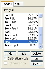
Notice that the percentage against Tex Right is zero, as it hasnt been calibrated yet.
Make Tex Right the link image for Side by holding down the Shift key while clicking on Tex Right.
Select Side image and zoom out to see all of the image.
Make sure that only the Right material is visible. Disable all other materials for now. Use the tick list in the Face tab to do this.
Tick the Calibration Mode checkbox to enter calibration mode.
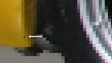
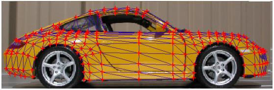
Click on a point behind the rear wheel as shown below.
Hold the shift key to show the linked image and zoom into the same point in that image, clicking where you think the point should be.
Here is where I have guessed it should go. The world will not end if this is not pixel perfect, as we are going to jiggle the image around later anyway.
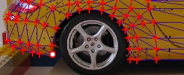
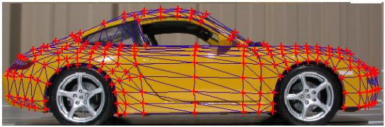
Repeat this process for easily known points like the front and back of both wheel arches and in the corners of windows etc as shown below :
Once you have a good spread of points (between 5 and 10 or so), untick the Calibration Mode checkbox to leave calibration mode.
The following popup will appear as the system finds the camera position. When its finished, the OK button will enable and we can move on.
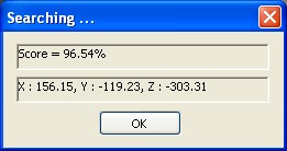
The image Tex Right should look something like this, which is roughly want we want :
Now we make it exactly what we want.
With Tex Right as the current image, enable calibration mode again and zoom into one of the wheel arches as shown below, click on a point that is not quite right and while holding down the left mouse button, drag the point to where it should be and release the mouse button.
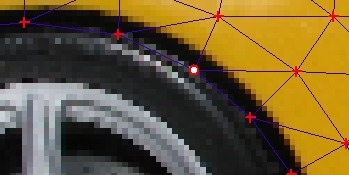
A new reference point should be created when you release the mouse button.
Dont create too many calibration points as the system will bog down trying to process them all. A few well placed ones are a good idea.
If a mistake is made, just select the errant reference point and press the delete key.
If you see the following popup appear, just press cancel. This happens when the mouse is clicked too far from the nearest point.
Here is the image after dragging a few points around :
Assign Texture
Ok, the texture image has been added and calibrated. Now we assign this texture image to the material Right.
Click on the Materials button on the toolbar.
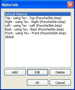
Select the material Right and click on the Edit button.
In the Texture map source dropdown list choose Tex Right.
The Materials list should look like this :
Press OK to finish with this form.
Apply Texture
To apply the texture to the model is really easy. Click on the Apply Texture button on the toolbar.
The screen should look like this :
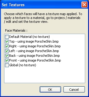
Press OK and we are done.
The system knows how to map the porscheskin.bmp to UV coordinates using the calibration mapping we did earlier.
Export
To see the result, click on the Export button on the toolbar and make sure you tick the Use Textures checkbox.
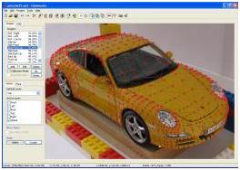
Here is the final result :
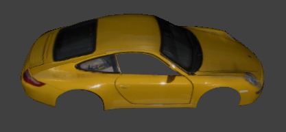
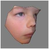
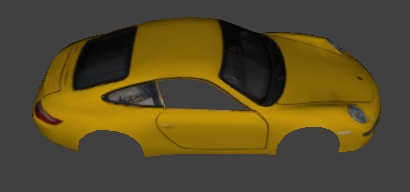
It would pay to tidy up the texture bitmap. The one above is straight from the camera, complete with flaring and reflections. The tutorial 6 directory contains an alternate skin called PorscheSkin2.bmp. By substituting the skin in the export file (using notepad and search and replace on the export file), the following is the result :
As usual, dont forget to save this project as something like Tutorial6a.op2 to keep the original tutorial project intact.