
LOW COST OPTICAL DIGITISING
| MENU | |
| Home | |
| Features | |
| Downloads | |
| About Rigs | |
| Purchasing | |
| How It Works | |
| Screen Shots | |
| Contact Us | |
| TUTORIALS | |
| Tutorial 1 | |
| Tutorial 2 | |
| Tutorial 3 | |
| Tutorial 4 | |
| Tutorial 5 | |
| Tutorial 6 | |
| Tutorial 7 |
Tutorial 4
This tutorial assumes that the user has already done tutorial1. This project is available on the downloads page.
The objective of this tutorial is to show how layers and materials can be used when creating a mesh.
Layers and Materials
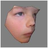
Open up the Tutorial4.op2 project file. This project contains all of the images required for the mesh. All of the images have already been calibrated.
Creating a Layer
The first thing that well do is to create a new layer. On the Project menu, select Layers. You can alternatively find the Layers button on the toolbar. Be careful not to use Set Layer. We will get to that one later.
On the Layers form, click the Add button.
Enter Side as a Description.
Click on the Colour button to choose a nice purple.
The screen should look like this :
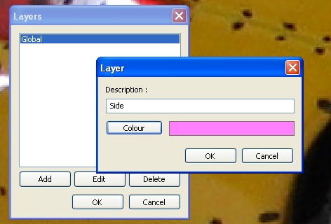
Click on the OK button to close the popup form, then click the OK button on the main Layer form.
Repeat the above exercise and create a layer called Back, with a colour of your choice. You can always edit these colours later if you change your mind. It can be handy to choose a colour that is contrasted to the model. Choosing yellow would be a bad choice for this model.
The Vertex tab in the tool pane should look something like this. Tick the new layers if they are not already set.
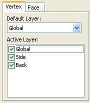
Setting the default layer
The default layer is the one that new points will be allocated to. All points must belong to a layer. The default layer is set in Vertex tab.
From the drop down list, choose Side.
Creating Points and Faces
We are now ready to create some points for our new layers.
Scrolling and zooming also works on the linked image. For example, while holding down the shift key (to show the link image), hold the CTRL key and move the mouse.
This project will use the images Side, Side Back and Back. These have been positioned at the top of the list to make accessing them easy. You can use the Up and Down button below this list to change the order at any time. Leave the list order as it is for now.
Click on the Side Image.
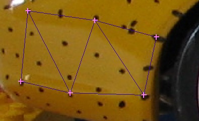
Press the Shift key to show the linked image and reposition both images so that points can be created between the wheel arch and the rear bumper area as shown below.
Make sure you are in Vertex Mode and Create Mode (select the Create button at the bottom of the tool pane).
Create some points.
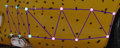
Click on the Face Tab to enter face mode and create some faces from the new points.
Your screen should look something like this. The actual point locations dont matter too much for this exercise, anywhere in this area would be fine.
Now click on the Back image.
On the Vertex tab, choose a default layer of Back.
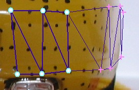
Create some points to extend the mesh around the corner as shown below.
Click on the Face tab to enter face mode and create some faces from the new points.
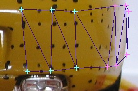
Note how the points are shown in the layer colour.
Check and uncheck the Side and Back Layers in Vertex Tab to see the effect on the model. Note how faces are only shown if all points are visible. The faces that straddle the 2 layers above are not drawn if either Side or Back are disabled.
Lets move on to materials
Creating Materials
Materials are like layers for faces.
On the Project menu, select Materials. You can alternatively find the Materials button on the toolbar. Be careful not to use Set Material. We will get to that one later.
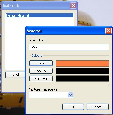
On the Materials form, click the Add button.
Enter Back as a Description.
Click on the Face button to choose a nice colour.
Leave the Texture map source. We will cover texture mapping in another tutorial.
The screen should look something like this :
Repeat the above exercise and create a layer called Side, with a colour of your choice. You can always edit these colours later if you change your mind.
The Face tab in the tool pane should look something like this. Tick the new materials if they are not already set.
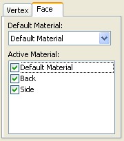
The Default Material drop down list can stay as is for now..
Setting Layers and Materials
The faces created so far belong to the Default Material material. We want to change the existing faces to use these new materials.
Choose the Face tab to enter face mode.
Press the Select button to enter select mode.
Use the mouse to drag a box selection around the points shown below. The selected faces are shown as bolded blue lines.
Press the Set Material button on the toolbar.
From the drop down list of materials, choose Back and press OK.
Press the Escape key to unselect all points.
Select the Side Back image and select the faces as shown below. Note how some of the back points have been selected to include the border faces.
Press the Set Material button on the toolbar.
From the drop down list of materials, choose Side and press OK.
Press the Escape key to unselect all points.
Exporting
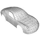
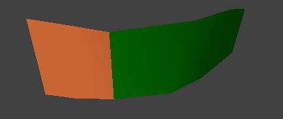
Export this mesh to a file and view the output. The following is Direct-X output in Mview.exe
Dont forget to save this project as something like Tutorial4a.op2 to keep the original tutorial project intact.
Faces are allocated to materials and points are allocated to Layers. This becomes important when allocating textures, as they are assigned to materials. See the Textures tutorial for more detail.